Objective: Controlling an output on a Revolution Pi system using CODESYS. The application flashes an external indicator lamp every second.
Two pre-programmed example projects for Blinking Light are available in the GitLab Repository. If you start with the ready-to-use example project, you can jump to Connecting with RevPi.
Prerequisites #
Devices #
✓ Base module of the RevPi Connect series or the RevPi Core series
✓ External LED indicator lamp
Hardware Installation #
✓ External indicator lamp is connected to the first output channel of the RevPi expansion module.
✓ RevPi base module and expansion module are connected via the PiBridge.
✓ RevPi base module is connected to the network.
✓ RevPi base module is connected to the power supply.
✓ RevPi expansion module is connected to the power supply.
See also Getting Started.
Software Installation #
✓ CODESYS Development System (CODESYS) is installed on your PC.
✓ CODESYS runtime is installed in the CODESYS Development System.
✓ RevPi I/O driver is installed in the CODESYS Development System.
✓ CODESYS is connected to the RevPi.
✓ CODESYS runtime is installed on the RevPi.
See CODESYS documentation about Setting up the System.
1. Creating a Project in CODESYS #
▷ Open CODESYS on your PC.
▷ Create a new standard project with CODESYS Control for Linux ARM/ARM64 and the required programming language.
The example projects use Ladder Logic Diagram (LD), a graphical programming language that is suitable for simple start-stop controls.

❯ A device tree is created in the Devices window.
▷ Open the context menu on the root device in the device tree.
▷ Select Add device.
❯ A list of all RevPi devices is displayed under Miscellaneous using the manufacturer filter KUNBUS GmbH.

▷ Select the appropriate RevPi device.
▷ Select Add device.
❯ The RevPi device is added to the device tree.
▷ Open the context menu of the piBridgeLeft or piBridgeRight object of the RevPi base module in the device tree.
|
Note
|
Only certain RevPi expansion modules can be connected on the right and left side to the RevPi base modules of the RevPi Connect and RevPi Core series. See also Rules for the Arrangement of Devices. |
▷ Select Add device.
❯ A list of RevPi expansion modules is displayed.
▷ Select the appropriate RevPi expansion module.
▷ Select Add device.
❯ The RevPi expansion module is added to the device tree.
See also documentation about Creating a Project Including RevPi Devices.
2. Assigning a Variable to the Output #
▷ Open the RevPi expansion module in the device tree.
▷ Navigate to the Mapping tab.
▷ Assign a user-defined variable name to the digital output DO_CH1 (boolean type) used for the LED.
❯ The output is accessed via CODESYS bit mapping.
Example with RevPi DIO:

In the example, the indicator lamp on channel 1 of the digital output of the RevPi DIO is mapped to the boolean variable Q_Lamp. It can be controlled directly in the program by setting Q_Lamp to TRUE or FALSE.
3. Writing the Program #
▷ Write a program in the required programming language and use the assigned variable.
In the example project the program in Ladder Logic Diagram is:
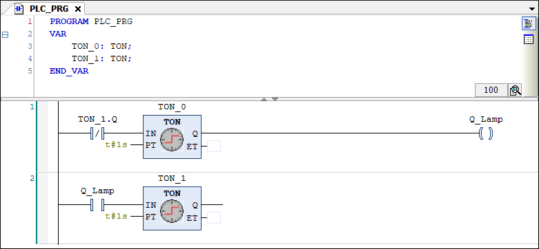
Functionality of the Blinking Light Example Program
Elements:
-
TON_0andTON_1are timers with a switch-on delay (TON = Timer On-Delay), which are configured with a period of 1 s. -
Q_Lampis the boolean variable mapped to the digital output for the indicator lamp on the RevPi DIO. -
TON_1.Qis the NC contact (only conducts ifTON_1has not yet expired).
Sequence:
-
TON_0starts, after 1 sTON_0.Qgoes TRUE andQ_Lampturns ON. -
TON_1starts, after 1 sTON_1.Qgoes TRUE, NC contact opens andQ_Lampturns OFF. -
TON_1TRUE blocks the NC contact in rung 1. -
TON_0resets and the cycle restarts.
Result: The two timers alternate so that the indicator lamp flashes every second (1 s on, 1 s off).
The ET field (elapsed time) of the timer is not required here and can remain empty.
4. Connecting with RevPi #
|
Note
|
In order to to connect to the RevPi device via CODESYS, it must be physically connected to your network and the CODESYS Runtime must be installed on the device. See Prerequisites. |
▷ Select Generate Code (F11) in the menu bar to compile the program.
▷ Open the root device.
▷ Select Scan Network in the Communication Settings.
▷ Select the RevPi and establish the connection to the device using OK.

▷ Select Login (AltF8) in the menu bar to log in to the RevPi.
▷ When you log in for the first time, create a user by following the wizard and entering your login details.
▷ In the Device User Logon window, log in to the RevPi.
▷ The first time, confirm the download of the application to the RevPi by Yes.
❯ The application is transferred to the RevPi and is ready to run.
5. Running Application #
▷ Select ⯈ (F5) in the menu bar to start the application.
❯ You are now in online mode, in which you can see the application logic executed cyclically in the task cycle.
❯ The indicator lamp connected to the RevPi expansion module should now flash every second.
Troubleshooting #
Errors can be detected in CODESYS in the CODESYS controller log.
▷ Select
The log file can also be called up in real time via an SSH terminal connection to the RevPi device using:
sudo tail -f /var/opt/codesys/codesyscontrol.log