


This clock is based on the ATSAML21E16B, a Cortex-M0+ microcontroller. The LTC4080
DC-DC converter handles both charging the battery and powering the CPU, both during the charging phase and regular operation. The CPU controls a 6×3 matrix of LEDs in multiplex and a buzzer through PWM.
The idea behind designing this circuit arises from the desire to combine the charm of Old Style pocket watches with LED technology.
I decided to go for a minimal design, opting for a LED matrix to display the time in binary format or as scrolling text.


The first step was to completely disassemble the pocket watch, remove all its mechanical components, and then accurately measure the available space inside the case in terms of both surface area and height. I then proceeded to design the electronic circuit that would adhere to all these constraints.
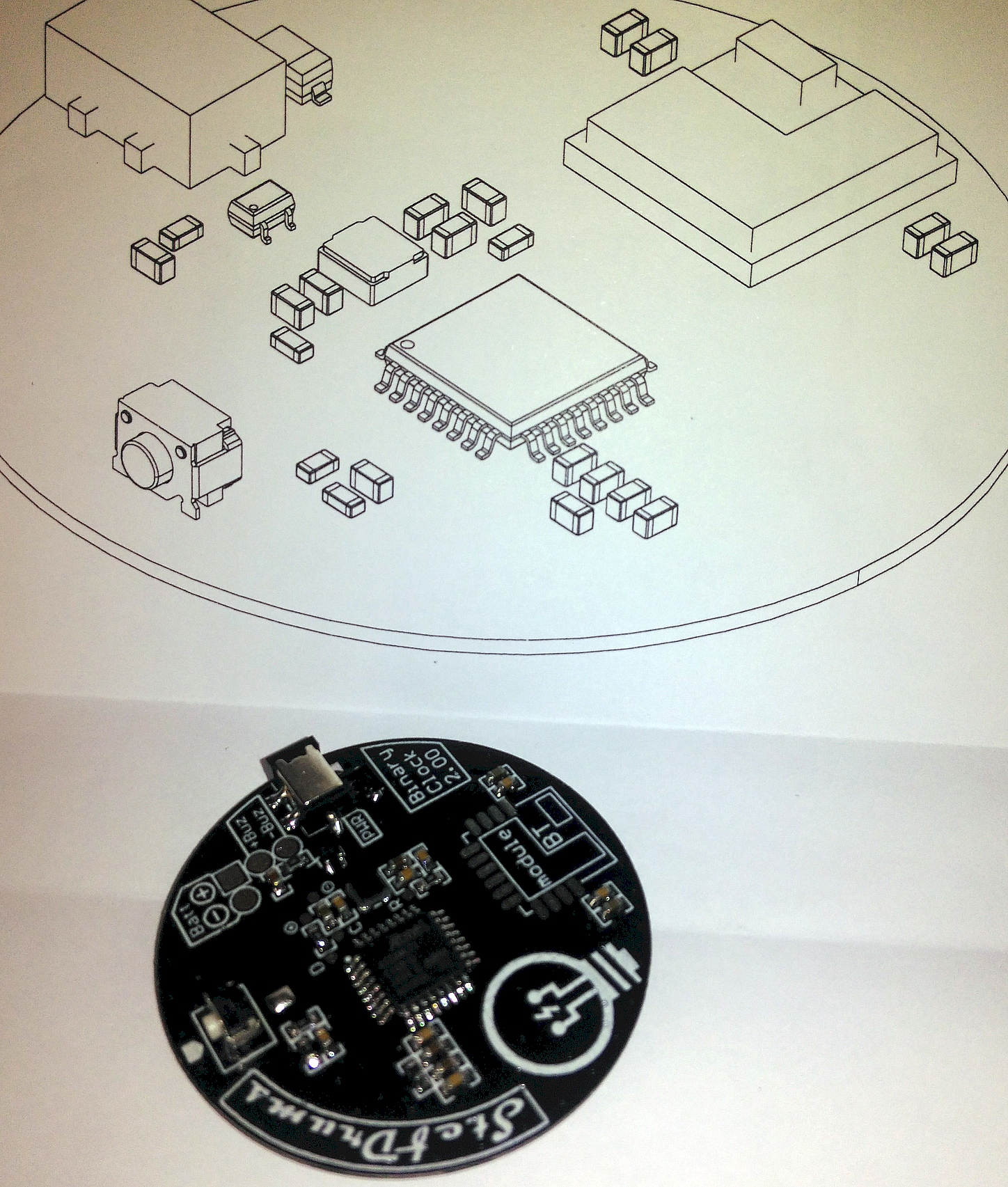
Once the circuit was designed, PCB was sourced from external supplier. All the components are soldered and now it’s time to insert it inte the case: the circuit perfectly fits!


During the firmware design phase, special attention was given to structuring the menus for setting the date, time, and all other parameters of the clock.
