MoteinoUSB R7 release

MoteinoUSB is now R7 and it comes with the following changes:

  • USB-C
  • Atmega328PB – to same specs and performance as Atmega328P
  • dedicated SMA/u.FL solder pads (3 pin header moved down to accomodate this)
  • CH340C USB serial chip – this is faster than the FTDI we’ve been used for ages, and it emulates the same serial port number (at least on Windows) which is nice when you have large numbers to program one after another (unless multiple are connected simultaneously – in which care different serial ports are emulated)
  • misc. other cosmetic tweaks and some routing optimizations
  • same price despite difficult market conditions (tariffs, increased mfg. costs, etc).

As usual, the optional add-ons enable this compact AVR based development board to become a wireless remote node that can control/monitor and live for years on a small battery.


Redesigned DDM Novastar Upgrade Kit & Demo

This is a short video that highlights the upgrade kit I designed for DDM Novastar L-BF-12 bank feeders. The OEM feeder cover tape management mechanism is time consuming, frustrating to use, and the more cover tape is spooled the less reliable the pickup becomes, causing the component to be advanced away from the trained location. This is all eliminated by my retrofit kit and is a huge time saver.

I also recently improved the design for the tape hold-down 3D printed plows for increased component pickup reliability – this helps with component tapes that have cover tape which is weakly attached and can prematurely detach or detach entirely. The new plow design solves that problem.

And finally got together a video demonstrating how easy and quick it is to change a short cut tape into a L-BF-12 feeder retrofitted with the upgrade kit I designed.

Contact me if you’re interested in such a kit.

RFM69 v1.6 breaking change: 433.0Mhz is now 433.92Mhz

Quick heads up for those in EU or regions where 433Mhz is legal (sometimes called 434Mhz). Since I never used straight 433Mhz with RFM69, other than in various tests and experiments, I was somewhat ignorant about this band.

Until … it was kindly pointed out by Angus Logan in this lib Issue, that 433.0Mhz is technically out of legal band. The TLDR; is that the center frequency for this band is actually 433.92Mhz. So the library was patched and the new v1.6 release is ready to upgrade in Arduino IDE.

Should you have a reason to revert to 433.0Mhz, for backwards compatibility to your other devices that might temporarily not be reachable otherwise (OTA update perhaps), you can always call radio.setFrequency(433000000) to set it back to 433Mhz, or any other frequency for that matter.

Other notable new changes in v1.6:

  • getVersion() to read RFM version
  • getAddress() to return configured node ID
  • getNetwork() to return configured network ID
  • getFrequencyDeviation() to read frequency deviation
  • getBitRate() to read the modulation bitrate in bits/second
  • getSpyMode() to return spy mode setting
  • isSyncOn()
  • getSyncSize()
  • isCrcOn() to check if CRC is activated
  • isAesOn() to check if encryption is enabled
  • isHighPower() to check if module is configured as HCW or not
  • dBm_to_mW() to convert dBm to mW
  • getOutputPower() to get the configured output power instead of returning the last
  • getTargetRssi() to get the configured RSSI value, only for RFM69_ATC
  • _networkID made public to get it via getNetwork() function

CurrentRanger R3 MK6

The CurrentRanger has been stable for the last few years with very positive feedback and very few issues that were addressed promptly, mostly firmware and a few minor hardware tweaks. The R3.MK6 revision has now already started shipping and notable improvements are as follows:

  • USB-C connector – more sturdy, non-polarized connector. A short USB-C cable is now also an optional add-on or available separately in the shop.
  • Default power button has been replaced with an SMD side button. This is actuated via a tab built into the case which has been tweaked to accomodate the USB-C and this new power button. The 3D model of this case is available here for those wishing to print their own. The kit also currently includes another SMD power button that can be soldered on top of the PCB where it used to be, in case this is useful or required in a test fixture.
  • Firmware is now at v1.1.4 and includes minor fixes reported by users. The CurrentRanger forum is the best way to report issues. The firmware UF2 is also on Github.
  • Optional 1200mAh battery specifically designed for CurrentRanger is now an optional add-on or available separately in the shop.

I hope these changes will be useful. As always, support is merely an email away. The forum is a good place to ask questions, report issues, propose improvements and share projects.

Fixing Microchip’s ICE cable

The Atmel/Microchip ICE programming cable for SWD/ICSP interfaces is junk. Someone decided to perhaps save a few pennies and design these ICE programmers with tiny 1.25mm pitch connectors that connect to cables that are prone to premature failure. The ICSP end is especially fragile with loose wires hanging in mid air, it’s very easy to damage it and won’t take any abuse. Even with gentle care the thin wires will just break inside the jackets and programming becomes intermittent then fails. Not to mention the spicy $37.40 plus S/H. The box it come in is a beauty to behold and has had proper attention but unfortunately doesn’t help with anything.

So to avoid this situation, or at least delay/alleviate it, I just extended the ICSP part of it and added proper DUPONT wires, and encapsulated the thin wiring in hot glue. I have some other ideas of how to fully do away with this cable but for now this is a quick hack.

I’m not sure why I’m documenting this but after becoming the proud owner of a failed cable worth $40+ and having to buy another, maybe someone at Microchip has a face palm moment and changes this into a more premium design worthy of the premium price tag.


RF range & performance testing in a concrete building

I needed a quick and easy (and slightly more professional) way to measure RF performance of the typical RFM69/RFM95 low power transmitters, at a remote location where a prospect RF sensor network would be installed. Here’s a video explaining the devices and what’s involved, the rest of the blog has more details, the code and links you might be interested in.

In the past I ran range and performance tests of RFM69 radios in various types of applications to gauge how it might perform. I know it does great in medium/large residential homes with many walls and gateway in a corner of a concrete basement, while nodes are transmitting from inside and outside the building 100-200ft away. It also works great in typical industrial buildings (usually metal) with lots of equipment and obstacles. Of course in practice we follow some basic RF principles to ensure our small antennas are oriented decently and signal not degraded by incorrectly crammed or wound inside enclosures.

At this location we had an unusual multi level heavily reinforced concrete building. I did not know what to expect – would all the concrete and rebar act as a faraday cage and totally block signal from an outside sensor to an inside gateway? Or would performance just be poor?

I assembled a MotionMote – which runs on a CR123A 3V lithium, sipping ~2uA. These batteries are great for temperature extremes, yielding a stable and deterministic discharge curve, and they can last for many years on an ultra low power node such as the MotionMote.

RFGateway is my go to board for setting up a RaspberryPi as an RF gateway. It plugs straight into a Pi’s USB port and I would normally use an SMA dipole antenna at the gateway end of such an RF network. The video shows how I soldered a helical to an SMA male connector to mate it to the RFGateway’s SMA-female connector.

The RFGateway’s SAMD51 processor clocks at 120mhz, plenty fast for handling packets from a very large RF network, while doing floating point and other memory operations. It has a small header convenient for an I2C OLED. Also for this evaluation I just used a LiPo battery plugged into the power header, only connected when USB is not plugged in.

Any compatible transceivers can be tested, but for this application RFM69HCW was used as I prefer it for all my RFM69 based applications.

To run the test I placed the small transmitting node (MotionMote) in a fixed position and walked away around the property and inside the building in the areas of interest with the RFGateway which displays the captured packets on the OLED. The transmitter sends a packet and waits for an ACK back from the RFGateway, that way we have 2-way communication for each transmission. Every few transmissions the RFGateway sends a packet to the node and waits for an ACK back (same as the normal transmissions but backwards).

The sample sketches are posted in the RFM69 library (RangeTest_Gateway & RangeTest_Transmitter). The video explains in more detail what the packets contain and how to evaluate the RF performance.

But essentially as signal gets weaker the RSSI will start to drop. The RFM69 library will automatically ramp up transmit power (that X metric) when signal drops too low.
So as I walk away from the NODE the RSSI will drop and the X will start to increase at some point. This helps determine any dead spots or areas with weak signal.

In my test the MotionMote was placed outside about 150ft away, and to my surprise there were no dead spots in the building either on above floors or below ground. The signal was weak as expected when I was below grade, but the RFM69_ATC auto-power was able to ramp up power and still reach the gateway. Below is one of the weakest signal spots with most grade and obstacles in the way, with signal still getting through, at the expense of higher transmission power at the node.

Have you built something similar? Let me know!

RFM69 TX power testing & library fix

The RFM69 library has been very robust and stable over the years. It is widely used in many hobby and home automation projects as well as research and commercial products. But that doesn’t mean we can’t find occasional things to fix and improve!

Is there a problem?

Recently, after renewed attention to a long time issue relating to power levels being incorrectly set, I took measurements and found the setPowerLevel() function was behaving somewhat unexpected. Instead of a smooth  Namely it as making available the lowest possible transmit power levels on the HW/HCW (aka high power) variants of RFM69. Since a commit in 2015 the 32 power levels were actually made into 16 steps and only using PA1+PA2 in high power mode. Not so much a loss except for those hoping to maximize battery life by running at the lowest power levels on the HCW – in which case they’d be better off using the CW instead. But this is enough to find a fix and take full benefit anyway of what the HCW has to offer.

Basic TX power testing

To produce power profile I put together a set of Transmitter and Receiver examples. To measure power output you can just use the transmitter sketch – it toggles TX mode and you can navigate the power levels from min to max. Below is a simple hardware test setup that can be used to take some power measurements: a CurrentRanger reads the current going into a Moteino+RFM69HCW that radiates an unmodulated carrier signal into a dipole. Idle MCU current (TX off) is read and then subtracted from total current with TX enabled:

To also measure RSSI (poor man’s power meter) we can just use another Moteino with the receiver sketch mentioned above, which will simply sample RSSI continuously (in RX mode), at a max AGC setting of -48dB to simulate a long “distance” since we’re doing all this in close proximity (the same room!). Open the transmitter sketch in a serial terminal and toggle TX mode with t and increase power with + & - in steps or < & > in dB – there is a new function setPowerDBm() in RFM69 library v1.5.0, in addition to setPowerLevel(). The CurrentRanger will show the current drained by the Moteino when transmitting at different levels and the RSSI on the receiver will also reflect different output power levels.

This setup produced the following power profile on the W/CW radio, nothing unexpected since there’s only PA0 to be used with no other registers to set, power levels being set in RegPaLevel.OutputPower. The only thing to notice is the ‘step’ in TX current and RSSI which indicates something’s definitely being switched inside the transceiver itself as _powerLevel crosses the middle of the RegPaLevel.OutputPower register, even if PA settings remain unchanged (only PA0 is used).

On the HW/HCW, in v1.4.3 (prior to the fix this blog is about) the power profile looked like this:

As it turns out the startup power is correctly set to a valid level 31, but calling setPowerLevel() even once results in values being set from 0-16 (all “forbidden” – see tables below) and never back to the original 31. This results in a ‘step ladder’ of transmit power levels vs. current. I know this sounds confusing, because it is.

The theory – datasheets and registers

To better understand what’s really going on, first we need to clear some confusion and understand that RFM69 radios have several possible transmitter PA (power amplifier) combinations for different output power profiles as outlined in the datasheet:

For W/CW radios things are very simple – only PA0 is wired to RFIO output pin and it can produce from -18 to 13dBm, corresponding to 32 possible power levels that can be set in RegPaLevel, as clearly reflected in the W/CW graph above.

For RFM69 HW/HCW radios things get more complicated, there are two possible PAs  and a power boost mode to be enabled to reach the highest output of 18 to 20dBm, according to section 3.3.7:

I know of only one other good article that outlines all this in detail, a blog by Andre Hessling, I found it accurate and so my focus is not to replicate that here, but rather use it as reference and complement for those wanting to get a full picture, so check it out if you want to get more in depth.

So!  The RFM69 library v1.4.3 and prior, has been only using PA1+PA1 in boost mode, at power levels 0-16, except at startup where _powerLevel was initialized and set to 31 and never divided by 2 like in setPowerLevel() – bug!.  In addition, the datasheet says levels below 16 are off limits for the PA1+PA2 combination, but because this works it went unnoticed for a long time, at least in my library (semi bug?). If you’ve read Andre’s article, you will notice PA1 alone can be used and he proposes using the following PA combinations for HCW:

  • PA1 (and PA1 only!) from -2 to 13 dBm output
  • PA1+PA2 from 14 to 17dBm output
  • PA1+PA1+HighPower for 18 to 20dBm

If we revisit the datasheet, we realize there is actually a power profile overlap between these 3 combinations:

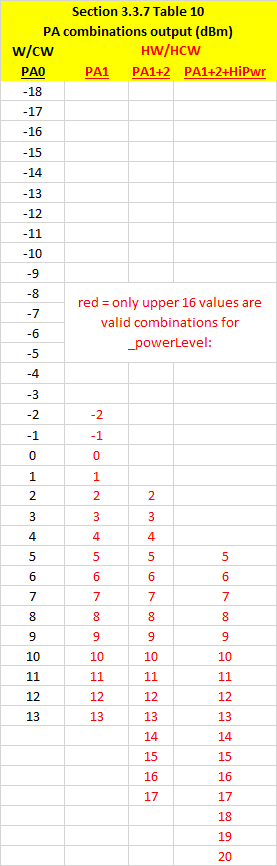
Notice for instance we can achieve -13dBm in 3 different ways on the HW/HCW:

  • using PA1 only with RegPaLevel.OutputPower=31
  • using PA1+PA2 with RegPaLevel.OutputPower=27
  • using PA1+PA2 with RegPaLevel.OutputPower=24

Enough already, what’s the conclusion?

Since theoretically the output is the same, it would be interesting to see the current profile against each of these as well. To cut this (really) short, I will link the spreadsheet with my tests and graphs and just mention the final conclusions. It matters which PA combination you pick, as a general rule, using more than one PA will result in higher current for the same effective transmitted output, at first this seemed counter intuitive but that’s what the meter and RSSI shows. I determined the best combination for HW/HCW to be the following:

If you notice, there are now only 24 _powerLevel‘s with slight overlaps between steps 14,15 and 16,17. The light orange band PA1+PA2 combination is sandwiched between PA1 and PA1+PA2+HighPower and helps optimize current used at those theoretical dBm outputs. This is similar but a little different than Andre’s proposed bands – I suspect he may have looked at RSSI but not at current used. Overall this produced the smoothest output power vs. RSSI vs. current curves that I could determine – with minimal ‘step’ jumps on the current and RSSI, and this is what we’d expect to properly use the power levels, especially in the RFM69_ATC extension which automatically regulates the power level based on a desired RSSI. And here are the measurements in a graph:

For the W/CW nothing really changes since there was no real issue, the graph will be the same as the first one included in this article.

Update the library and test on your own!

I made a new release v.1.5.0 which should address all these issues and includes the TX power testing examples which can be used by anyone with perhaps different/better test setups to verify these findings. Please update  and try this out. I may update this blog with further info if need be in the future since it’s more of a reference for RFM69 PA modes.

CurrentRanger updates

Thanks to MGX3D there are now some nice improvements to the CurrentRanger:

  • Firmware updates and optimizations, battery icon instead of text (faster drawing)
  • Improved sampling speed
  • Smarter Auto-Off – avoids turning off when sampling via USB
  • more menu items and options
  • Fusion360 models now available, see this page for links

There is also a new improved OLED enclosure model designed by MGX3D as well. This is also available to pick up in the webshop or you can print your own – models available here and here.

There is now also a python based graphic visualization GUI designed by MGX3D and available here on Github, check out its features and specs on Github, mainly it brings the ability to view serial data from the CR in logarithmic scale and also in autoranging mode, w00t! Here’s a preview of that GUI available for Windows/Linux (and MacOS planned):

A word on using the CurrentRanger

It seems some folks are too excited to try it out and miss reading some of the guidelines on proper usage, this is really important not to overlook. I have seen a few strange cases of abused units that were returned. It turns out it’s never a DOA condition or anything related to a real fault. All units are tested, calibrated, turned ON/OFF etc, to ensure they are functional. Faults are usually a case of improper use, improper soldering or attaching of headers and terminals which cause damage to SMD components, the OLED, etc. Here’s an example of how to not solder the OLED header, or at least not how to leave the board after a solder job, this will cause all kinds of problems (corrosion, possible leaks and faults on the board):


Finally, I would like to express my gratitude for the feedback and positive response and interest into CurrentRanger. When used properly with love and care, it is an amazingly versatile and ultra-portable tool that will work for many years without any trouble. There are plans to make it even better and constructive feedback is always welcome and encouraged. Don’t forget that WELECTRON Germany is now our official distributor in Europe and carries the CurrentRanger as well as many other products.

DDM Novastar L-BF-12 Feeder upgrade

Over the past year or so I spent a lot of time designing and iterating over a new upgrade for my pick & place. The result is an upgrade kit that can be installed without modifying the original feeder. It enables the bank feeders in my DDM Novastar LE40-V to no longer have to peel back the cover tapes. That alone is a huge benefit. Watch this video of this upgrade in action, and see what other benefits this new concept brings to the L-BF-12 bank feeder.